Section 2.1 Coordinate Spaces and Robot Pose

To control a mobile robot, we must first describe where it is in the world and which way it is facing. In 2D planar kinematics, we represent the robot’s state using a Pose vector \(\mathbf{q}\text{:}\)
\begin{equation*} \mathbf{q} = \begin{bmatrix} x \\ y \\ \theta \end{bmatrix} \end{equation*}
  • Position \((x, y)\text{:}\) The 2D Cartesian coordinates of the robot’s reference point (usually the center of the wheel axle) relative to a fixed Global Frame (\(W\)).
  • Heading \((\theta)\text{:}\) The orientation angle of the robot’s heading relative to the positive \(x\)-axis, measured in radians.
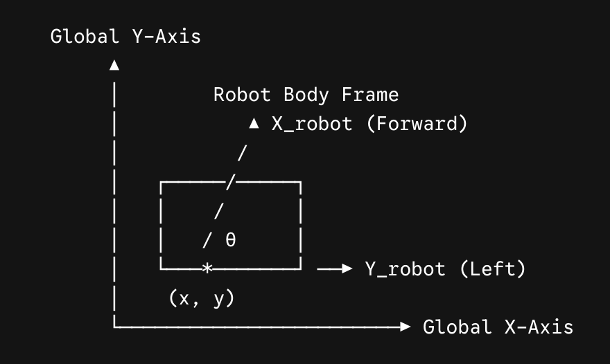
Picture the robot as a small rectangle sitting at position \((x, y)\) in a fixed global grid. An arrow drawn out of its front edge, the robot’s own forward direction, is rotated by the heading angle \(\theta\) away from the global \(x\)-axis, and a second arrow pointing out of its left edge marks the robot’s own left direction.
Why bother with a formal pose vector at all? Because every question a robot needs to answer—"How far am I from the goal?", "Is that obstacle to my left or right?", "Did I actually turn 90 degrees like I commanded?"—is meaningless without a shared, numerical frame of reference. A human can point and say "over there," but a robot’s motor controller only understands numbers. The pose vector \(\mathbf{q}\) is the single, unambiguous answer to "where am I, and which way am I facing?" that every algorithm in this book, from odometry to path planning, is built on top of.
Figure 2.1.1. A robot pose \((x, y, \theta)\) expressed in the global coordinate frame, with the robot’s forward and left body-frame axes.

Subsection 2.1.1 Local Body Frame vs. Global Frame

  • Global Frame \((W)\text{:}\) A fixed reference frame attached to the room or arena floor.
  • Robot Body Frame \((R)\text{:}\) A moving reference frame fixed to the robot’s chassis. The positive \(x_R\)-axis points in the robot’s forward direction, and the \(y_R\)-axis points to the robot’s left.

Subsection 2.1.2 Translating Body-Frame Velocity into the Global Frame

To translate velocity commands from the robot’s body frame (forward velocity \(v\) and angular velocity \(\omega\)) into motion in the global frame \((\dot{x}, \dot{y}, \dot{\theta})\text{,}\) we use the rotation matrix:
\begin{equation*} \begin{bmatrix} \dot{x} \\ \dot{y} \\ \dot{\theta} \end{bmatrix} = \begin{bmatrix} \cos\theta & 0 \\ \sin\theta & 0 \\ 0 & 1 \end{bmatrix} \begin{bmatrix} v \\ \omega \end{bmatrix} \end{equation*}
This matrix rotates the robot’s own forward speed into global \(x\) and \(y\) components based on its current heading \(\theta\text{,}\) while angular velocity \(\omega\) updates heading directly.
Notice what the matrix is really doing conceptually: it is a translator between two languages. The robot only ever "feels" its own forward speed \(v\) and turning rate \(\omega\)—it has no innate sense of North or East. The rotation matrix takes that self-centered description and re-expresses it in the map’s language, so that the robot’s motion can be tracked and plotted on a fixed field or floor plan. Every time \(\theta\) changes, the "translation" changes too, which is exactly why heading must be updated continuously, not just once at the start.

Subsection 2.1.3 Real-World & VEX AIM Examples

Real-World Example (GPS Navigation & Self-Driving Cars): When a phone’s map app shows a moving blue dot, that dot’s position is a pose expressed in a Global Frame—latitude and longitude converted into local \(x, y\) meters. But the car’s own onboard sensors, like a forward-facing camera or LiDAR, report everything relative to the car’s Body Frame: "the pedestrian is 5 meters ahead and 2 meters to my left." Self-driving software constantly converts between these two frames, exactly like the rotation matrix above, so that a body-frame detection ("obstacle ahead of me") can be placed correctly on the global map, and a global-frame destination ("turn left on Main Street") can be turned into a body-frame steering command.
VEX AIM Robotics Example: A VEX AIM robot’s onboard odometry system continuously estimates its own pose \(\mathbf{q} = [x, y, \theta]^T\) relative to a fixed origin, typically a corner or center of the competition field. This lets an autonomous routine give a command as simple as "drive to field position (24, 36) inches," even though the robot has no idea where that point is in body-frame terms until it converts its current pose into the field’s Global Frame. Without a shared coordinate space, the robot’s drivetrain would only ever know "spin the left motor" and "spin the right motor"—it would have no concept of a scoring zone’s location on the field at all.

Subsection 2.1.4 Section 2.1 Interactive Exercises

Subsubsection 2.1.4.1 Exercise 2.1.2: CodeLens Trace — Global Pose Update

Step through the code below to see how a robot’s local body velocity translates to updates in global frame coordinates.

Reading Questions 2.1.5 Reading Questions

Check your understanding

1. Exercise 2.1.1: Coordinate Frame Orientation Conceptual Check.

A robot is located 3 meters east (\(x\)-axis) and 4 meters north (\(y\)-axis) of the origin, facing directly North (along the positive \(y\)-axis). What is its pose vector \(\mathbf{q} = [x, y, \theta]^T\text{?}\)
  • \((x = 3.0,\ y = 4.0,\ \theta = 0.0 \text{ rad})\)
  • Incorrect. \(\theta = 0.0\) radians points along the positive \(x\)-axis (East).
  • \((x = 3.0,\ y = 4.0,\ \theta = 1.571 \text{ rad})\)
  • Correct! \(\theta = \frac{\pi}{2} \approx 1.571\) rad points directly North along the positive \(y\)-axis.
  • \((x = 4.0,\ y = 3.0,\ \theta = 3.141 \text{ rad})\)
  • Incorrect. The position values \(x\) and \(y\) are swapped.
  • \((x = 3.0,\ y = 4.0,\ \theta = -1.571 \text{ rad})\)
  • Incorrect. \(\theta = -\frac{\pi}{2}\) rad points South along the negative \(y\)-axis.
You have attempted of activities on this page.