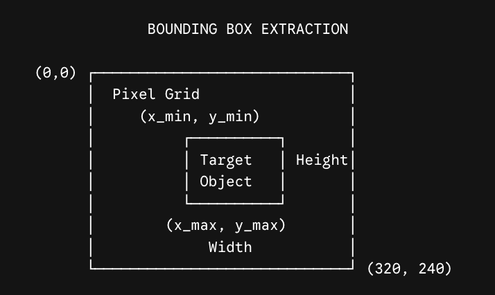
Once color thresholding or a neural network isolates target pixels (e.g., all pixels corresponding to a game piece or hazard), the robot must convert those scattered pixel clusters into a structured geometry it can use for spatial navigation and manipulation.
Picture a small grid where a cluster of target pixels marked X occupies columns 2–4 and rows 1–2, with every other cell empty. The bounding box for that cluster is the rectangle spanning exactly those occupied cells: \(x_{\min} = 2\text{,}\)\(x_{\max} = 4\text{,}\)\(y_{\min} = 1\text{,}\)\(y_{\max} = 2\text{.}\)
From these four values, the robot’s onboard processor instantly calculates key geometric properties without needing to process thousands of raw individual pixels:
Picture the bounding box as a rectangle anchored at \((x_{\min}, y_{\min})\) in its top-left corner and stretching to \((x_{\max}, y_{\max})\) in its bottom-right corner, with its width \(W\) running along the top edge, its height \(H\) running along the left edge, and its center point \((C_x, C_y)\) sitting exactly in the middle.
Proximity & Visual Servoing: The width and height of the bounding box provide an immediate estimate of relative distance (as an object gets closer to the camera, its bounding box grows larger in pixel space). The center point \((C_x, C_y)\) determines if the obstacle is directly ahead or off to one side, triggering steering adjustments.
A distant object produces a small bounding box; as that same object approaches the camera, its bounding box grows larger and larger in pixel space, giving the robot a simple visual proxy for closing distance.
Subsubsection6.3.1.2Competition Robotics: VEX AI Vision Sensor
In the VEX AI Competition (VAIC) and modern VEX V5 robotics platforms, robots use onboard vision hardware like the VEX AI Vision Sensor or V5 Vision Sensor to autonomously score game elements (such as rings, triballs, or blocks).
Centering the Intake: The robot compares the bounding box center \(C_x\) to the camera frame’s optical center (e.g., \(X = 160\) on a \(320 \times 240\) sensor).
Distance Estimation: When width reaches a target pixel value (e.g., 200 pixels wide), the robot knows the ring is directly inside its intake rollers and closes its mechanical clamp.
For example, within a \(320 \times 240\) camera frame with its center line at \(X = 160\text{,}\) a target ring detected with a bounding box center of \(C_x = 70\) sits well to the left of center, so the robot turns left to bring the ring toward the middle of the frame.
Consider the \(5 \times 5\) binary pixel grid below from a camera sensor tracking a VEX game piece. 1 represents target pixels and 0 represents background pixels. Pixel coordinates are formatted as \((x, y)\) where \(x\) is the column index (0…4) and \(y\) is the row index (0…4).
Implement the target-tracking logic used on a VEX AI robot. Given a camera frame width of 320 pixels and a detected object’s bounding box parameters (x_min, x_max), calculate \(C_x\) and output the correct drive command ("TURN_LEFT", "TURN_RIGHT", or "DRIVE_FORWARD").
Subsubsection6.3.2.3Exercise 6.3.4: Parsons Problem — Bounding Box Calculation Algorithm
Reorder the steps below to create a logical Python function structure for computing a bounding box and center point from a list of detected \((x, y)\) pixel coordinates.
Arrange the blocks to form a complete function compute_bounding_box_and_center that returns the top-left corner, bottom-right corner, and center point of a set of pixel coordinates.
A VEX AI robot camera has a horizontal resolution of 320 pixels (screen center is at \(X = 160\)). The vision sensor detects a game element with a bounding box extending from \(x_{\min} = 200\) to \(x_{\max} = 260\text{.}\) What action should the robot’s alignment controller take to center the object?
Turn right, because the bounding box center \(C_x = 230\) is to the right of the screen center.
Correct! \(C_x = 200 + (260-200)/2 = 230\text{.}\) Since \(230 > 160\text{,}\) the object is on the right side of the frame, so the robot must steer right to center it.
Drive straight forward, because the object is already perfectly centered.
Incorrect. \(C_x = 230\) is well to the right of the screen center at 160, not centered.
Stop completely, because \(x_{\max}\) exceeds the screen limit.
Incorrect. \(x_{\max} = 260\) is within the 320-pixel-wide frame, so nothing exceeds the screen limit.