Section 19.5 Class Diagrams
When two classes are involved in an inheritance or composition relationship, we say that an association exists between them. Often it is helpful to depict the associations between classes on a graphical diagram, so that developers working on the code can see at a glance how the classes are related to each other. The Unified Modeling Language (UML) is a graphical notation that provides a standard for depicting classes and their associations on various types of diagrams. It gives software engineers a way to record both their proposed designs, as well as the design of the final product. Put another way, UML provides the notation for constructing blueprints for software, and since it is widely used in both industry and academia, it is important for you to have some familiarity with it.
UML defines notations for several different kinds of diagrams. Here, we will introduce class diagrams, one of the most common UML diagrams. Class diagrams can contain a number of different elements, but we will focus on the basics: depicting classes with their instance variables and methods, and relationships to other classes.
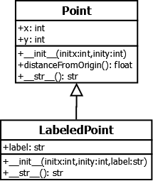
On a UML class diagram, a class is depicted as a rectangle with three sections. The top section contains the class name; the middle section, the instance variables; and the bottom section, the methods. The following diagram shows the classes Point and LabeledPoint in their original inheritance relationship.
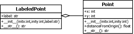
To depict composition, UML uses a different type of association, as shown in this figure:
You have attempted of activities on this page.
