The search methods we will be dealing with in this chapter are defined on trees and graphs, so we must first go over what trees are and how they work. Throughout this section, we will use the following tree as a guiding example for visualizing the definitions.
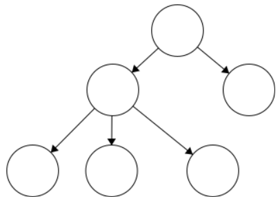
A simple tree diagram showing a hierarchical structure. The diagram is composed of six empty, unlabeled circles. At the top is a single circle with two arrows branching left and right into two more circles. The left circle then branches further into three more circles arranged side-by-side at the bottom. All arrows connecting these circles are pointing strictly downward, indicating the direction of the hierarchy.
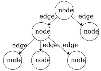
The same hierarchical tree diagram from the previous figure, with all structural elements now labeled. Every one of the six circles in the diagram is labeled with the word "node." Every arrow connecting these circles is labeled with the word "edge." This provides a clear visual distinction between the two fundamental components of the tree: the points of data storage (nodes) and the directional connections between them (edges).
This tree has five edges and six nodes. There is no limit to the number of nodes in a tree. The only stipulation is that the tree is fully connected. This means that there cannot be disjoint portions of the tree.
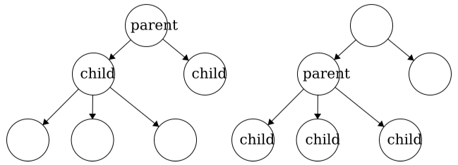
Child node — a node that is a direct successor of another node. In a general tree, the children of a node are an unordered set. There is not a fixed or defined order for generic trees. Child nodes must have exactly one parent node. However, there is no limit to the number of child nodes a parent node can have, but to be a parent node, the node must have at least one child node.
Two identical hierarchical tree diagrams placed side-by-side, demonstrating parent and child relationships using different reference points. In the tree on the left, the topmost node is labeled "parent," with two edges branching down to two nodes, both of which are labeled "child." In the tree on the right, the topmost node is empty. The left node, which receives an edge from the top, is labeled "parent." This node branches down into three nodes at the bottom, all of which are labeled "child." Together, these two diagrams show that a "parent" node is simply one that has direct successors, while a "child" node is a direct successor of another node.
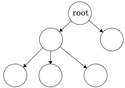
Root node — the topmost node of the tree that has no parent. To be a tree, there MUST be only one root. Also, a tree consisting of only a single node is still considered a tree and that single node would be the root.
The same hierarchical tree diagram from the previous figures, with one label applied. The single node positioned at the very top of the structure—which has no incoming arrows—is labeled "root." This node acts as the entry point for the entire tree. The rest of the nodes remain empty, with the root node branching down into the rest of the hierarchy, illustrating that a tree must have exactly one root node.
A rule of thumb for discerning trees is this: if you imagine holding the tree up by the root and gravity took effect, then all edges must be pointing downward.
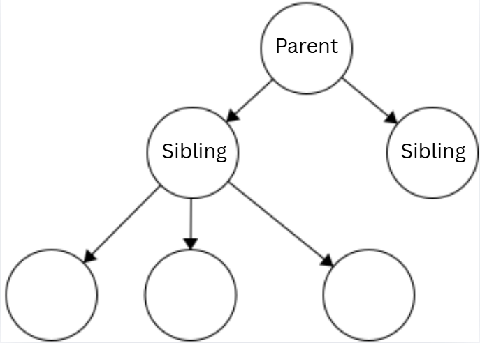
The same hierarchical tree diagram, now used to demonstrate the concept of siblings. The root node is labeled "Parent." From this parent node, two edges branch downward to two separate nodes. Both of these direct child nodes are labeled "Sibling." This visual shows that siblings are nodes that share the exact same parent.
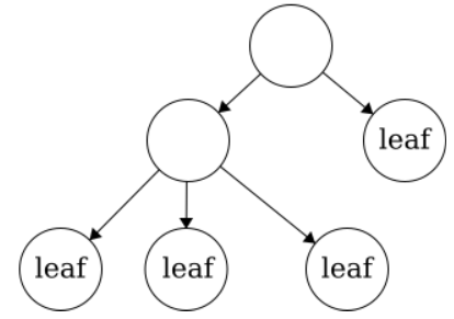
The same hierarchical tree diagram, illustrating leaf nodes. The four nodes located at the very ends of their respective branches—meaning they have no outgoing arrows pointing to any other nodes—are each labeled with the word "leaf." All the parent nodes remain unlabeled, demonstrating that leaves are strictly nodes at the bottom of a tree.
Subsection3.1.2Real World Application of Tree Structure
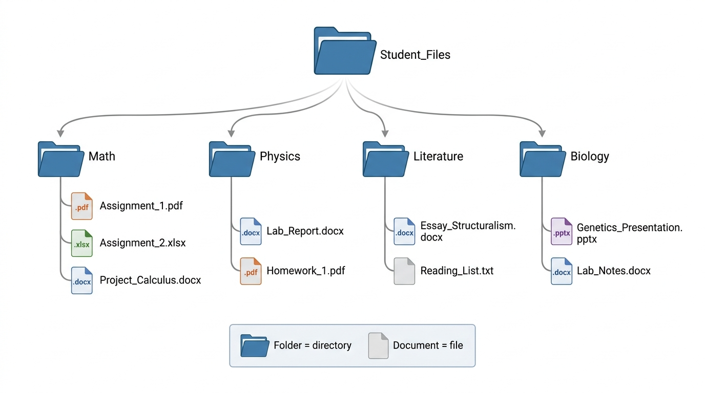
Many operating systems use a tree structure to organize your directories, folders, and files. Some of you may have a folder, within afolder, within a folder, that leads to your assignments files. The files you reach from a folder would be considered the leaf nodes while the folder(s) that got you to those files would be the parent nodes. Here is a visual of how the files and folders may look as a tree.
A tree diagram demonstrating a directory structure commonly used in operating systems. At the top, a root folder icon labeled "Student_Files" branches down into four separate subfolder nodes: "Math," "Physics," "Literature," and "Biology." Each of these subfolders acts as a parent node to various file nodes listed beneath them. The files consist of homework, projects and assignments. A box at the bottom of the image clarifies that blue folder icons represent directories, while white document icons represent files. All files are positioned as leaf nodes at the bottom of their branches.
The difference between trees and graphs is that trees are connected (every pair of nodes has a path between them), and all nodes in a tree must descend from the root in a hierarchy where each node only has one parent. This also means that trees are a subset of graphs (all trees are graphs but all graphs are not trees).
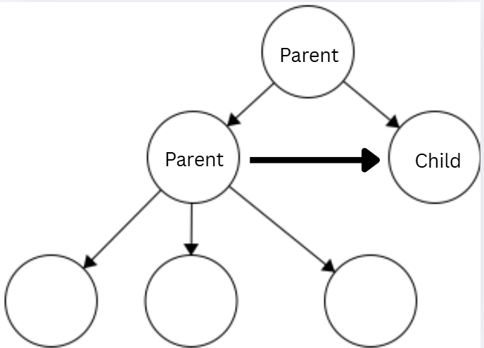
The same graph stucture with specific nodes labeled to demonstrate a parent-child relationship. The upmost node is labeled "Parent", and branches down left and right to two separate nodes. The left node is also labeled "Parent," and a bolded arrow points horizontally from this left "Parent" node to the right node, which is labeled "Child." This bolded arrow highlights that the node can be a direct descendant of more than one node.
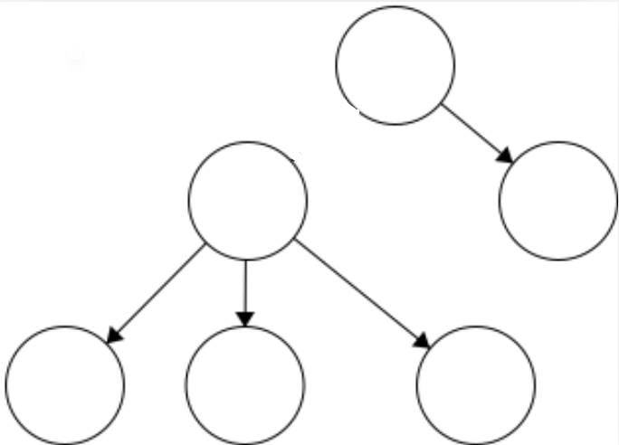
A graph diagram showing two completely disjoint structures. On the right, a single vertical pair of nodes is connected by a downward arrow. On the left, a larger five-node structure branches into a hierarchy. There is no arrow or edge connecting the two components, illustrating that the graph is disconnected.