5.2. The AND Gate
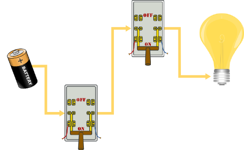
By changing the way wires run between our switches (the inputs) and the light (output), we can perform different Boolean operations. The circuit below demonstrates the Boolean rule AND. Notice that because there is one pathway through both switches from the battery to the light bulb, both switches must be in the on position to light the bulb:
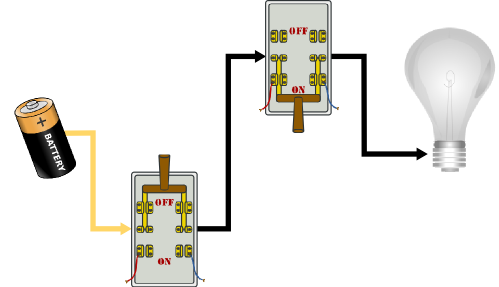
If either switch is off, that stops the current and the output is 0 (off):
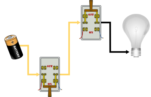
What happens if both switches are off? If the first switch is off, the current is stopped there - it doesn’t really matter what state the second one is in, we know the output will be 0. Once again we can express this as a truth table. Note that we have the same four possible sets of inputs that we had for the OR gate: 00, 01, 10, or 11 - any truth table describing a two-input circuit will always have those four possible inputs. What is different for the AND gate is the outputs produced by each input - it outputs a 1 only when both inputs are 1:
Input 1 |
Input 2 |
Output |
|---|---|---|
0 |
0 |
0 |
0 |
1 |
0 |
1 |
0 |
0 |
1 |
1 |
1 |
Once again, the 1’s and 0’s can represent any Boolean (true/false) information. For instance, we could express the logic for determining whether or not a student got a B with this rule: “If your grade is greater than or equal to 80 AND your grade is less than 90, then you have a B”. The AND combines two true/false ideas (“your grade is > or = to 80”, “your grade is < 90”) into one result (“you have a B”). If either of the two facts is false (your grade is less 80 or it is 90 or above), then you do not have a B.