
Section 4.2 Fire alarm using flame sensor
Subsection 4.2.1 Introduction

Fire accidents are common disasters in India. According to the report of ADSI in 2019, 11,037 fire accidents have been reported across the nation. These kinds of disaster may lead to loss of lives. To avoid this kind of disaster, fire alarm is used as an effective system to prevent fire accidents. Nowadays there is enough security to save the people from Fire accidents. It is used in many countries to save the lives of the people from fire accidents. It Monitors the environment and helps the people to know when there is a fire accident. Flame detector is the vast application to use in industries which are easily exposed to fire. Flame detector is used to prevent forest fire. Here a small prototype model is developed to detect the fire using flame sensor and alarm the people Table 4.2.1, illustrates the components required for the fire alarm is listed with its purpose
Subsection 4.2.2 Components required
| S. No | Name | QTY | Purpose |
| 1 | Arduino UNO | 1 | Arduino Board is used to read the digital inputs and convert it as digital outputs.(Refer Chapter 1.3) |
| 2 | Flame sensor | 1 | Sensor used to detect presence of fire |
| 3 | Resistor | 1 | Reduces the flow of the current and divide the voltage (Refer Chapter 2.1) |
| 4 | LED | 1 | Visualizes the feedback of the current for any application (Refer Chapter 2.1) |
| 1 | Buzzer | 1 | It is mainly used as warning tone, will alert the people if there is an emergency. (Refer Chapter 2.2) |
| 6 | Jumper Wire | As per requirement | Jumper wires are used to connect the components with Arduino UNO Board. |
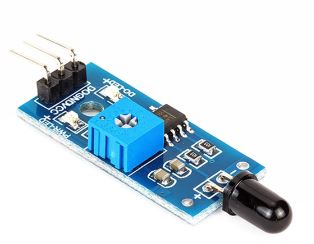
Subsubsection 4.2.2.1 Flame sensor
A flame-sensor is a kind of detector which is mainly designed for detecting as well as responding in occurrence with fire. This sensor is used mainly in industrial boilers.The speed of these sensor is faster and more accurate when compared with a smoke detector. Fig 4.2.2, displays the image of the flame sensor. Table 4.2.3 displays the pin configuration of the sensor with its following purpose.
| S. No | Name | Purpose |
| 1 | AO | Analog pin detect the presence of fire in the environment |
| 2 | GND (-) | GND of the Power supply |
| 3 | VCC (+) | Power pin is usually connected to 5V |
Subsection 4.2.3 Experimental Approach
Aside
-
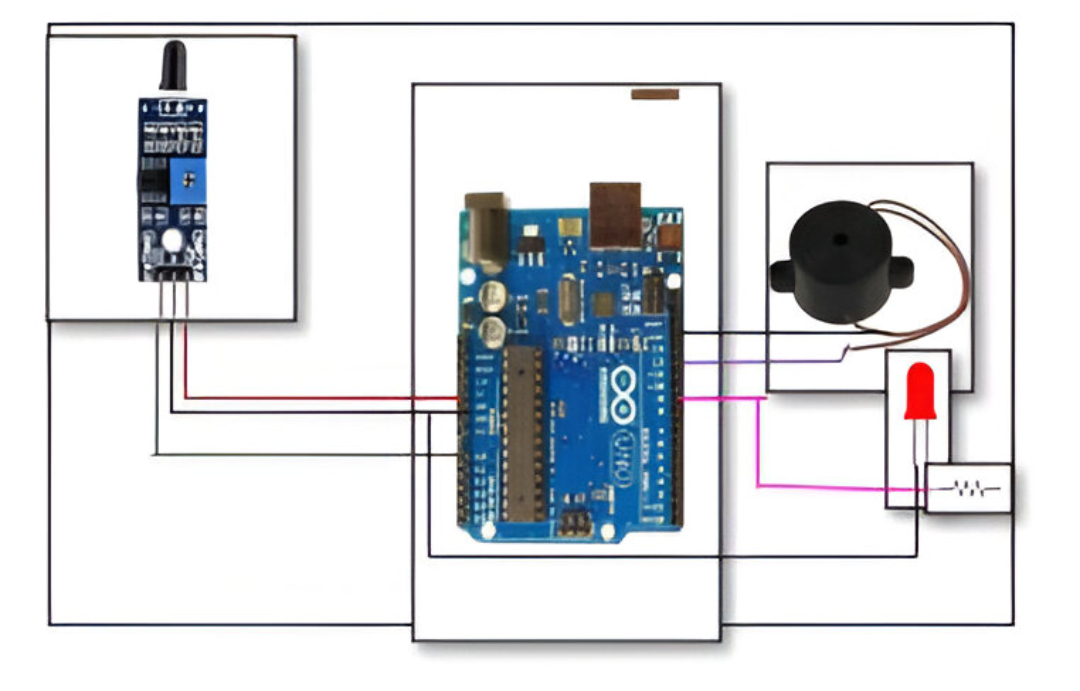
Analog pin of flame sensor is connected to A0 pin of Arduino.
-
VCC of the sensor is connected to 5V of the Arduino.
-
GND of the sensor is connected to GND of the Arduino.
-
Buzzer has two pins positive and negative pin.
-
Positive red wire is connected to 12th pin of the Arduino.
-
Black wire of the buzzer is connected to GND of the Arduino.
-
Longer leg of the LED pin is connected with Arduino through a 10k resistor.
-
Shorter leg of Arduino is connected to ground of the LED.
-
When the value exceeds threshold 100 it indicates there is a smoke/fire in the environment buzzer will trigger an alarm to alert people.
| Arduino Pins | Component Pins |
| A0 | A0 (Flame) |
| 5V | VCC(+)(Flame) |
| GND | GND(-)(Flame) |
| D12 | + (Buzzer) |
| GND | GND (Buzzer) |
| D9 | + via 1k |
| GND | GND |
Subsection 4.2.4 Code
Source Codeint sensorPin = A0; // select the input pin for the flame
int sensorValue = 0; // variable to store the value coming from the sensor
int led = 9; // Output pin for LED
int buzzer = 12; // Output pin for Buzzer
void setup() {
// declare the ledPin and buzzer as an OUTPUT:
pinMode(led, OUTPUT);
pinMode(buzzer,OUTPUT);
Serial.begin(9600);
}
void loop()
{
Serial.println("Welcome");
sensorValue = analogRead(sensorPin);
Serial.println(sensorValue);
if (sensorValue > 100)
{
Serial.println("Fire Detected");
Serial.println("LED on");
digitalWrite(led,HIGH);
digitalWrite(buzzer,HIGH);
delay(1000);
}
digitalWrite(led,LOW);
digitalWrite(buzzer,LOW);
delay(sensorValue);
}
-
Declaring variables of Flame sensor to sensor pin A0, Buzzer to 12th pin, LED to 9th pin .
-
In void setup () declaring the output pins LED, Buzzer pin using Pin Mode function.
-
Be sure which of the following acts as input and output pin, For example, pinMode(led, OUTPUT);
-
In void loop function, using analogRead function will convert the flame value generated from the sensor to analog value.
-
Generated analog value will be stored in an integer variable.
-
This prototype will work according to the following condition, when the presence of the fire is less than 100 the LED remains in on state and buzzer will alert the people or else the LED, Buzzer remains in off state.
Subsection 4.2.5 Experimental Result
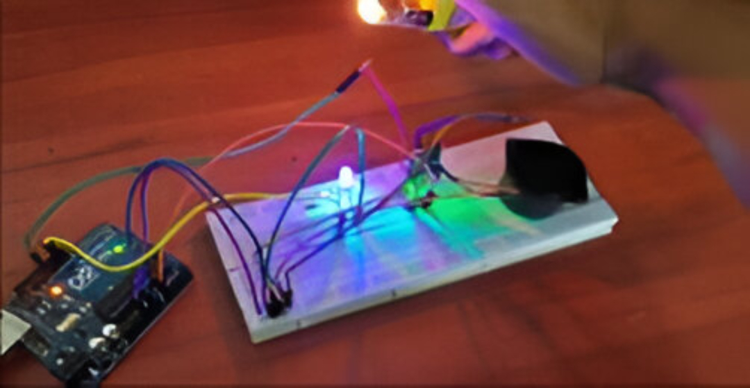
When the value of the flame sensor is higher than the threshold, i.e., when the value is greater than 100, LED will blink in association with the buzzer to indicate the people in the surrounding.
You have attempted of activities on this page.
