
Section 3.5 Smart Street Light System
Subsection 3.5.1 Introduction
Street light plays a major role for security in urban areas. The street light will also improve the safety for drivers, riders and pedestrians. Half of the energy of the city is used for the electricity, is used for street light consumption. Sometimes during the dawn, the street light will be on for a longer time, this will eventually lead to wastage of electricity. To avoid this kind of problems, the smart street light will be used to power on or off the street light based on light intensity of the sunlight and based on the presence of the object. In this experiment LDR sensor and IR sensor is used. It is prototype model so only 2 IR sensors and 1 LDR sensor is used if needed can expand this to large scale by expanding the number of sensors. The table 3.5.1 lists the components required for the smart street system. It minimizes the electricity consumption and provides appropriate electricity only when needed
Subsection 3.5.2 Components Required
| S.No | Name | QTY | Purpose |
| 1 | Arduino UNO | 1 | Arduino Board is used to read the digital inputs and convert it as digital outputs. (Refer chapter 1.3) |
| 2 | LDR sensor | 1 | LDR is used to measure the Light intensity of the atmosphere |
| 3 | IR Sensor | 2 | IR sensor detect the presence of IR waves emitted by human body(Refer chapter 3.3) |
| 4 | LED | 2 | Visualizes the feedback of the current for any application (Refer chapter 2.1) |
| 5 | Jumper Wire | As per requirement | Jumper wires are used to connect the components with Arduino UNO Board. |
Subsubsection 3.5.2.1 LDR Sensor
LDR Sensor is also called as photo resistor. It works based on principle of photoconductivity. There is a passive component in the sensor which act as resistor whose resistance value will increase when the intensity of the light increases. From the fig 3.5.2 image of the LDR is displayed.
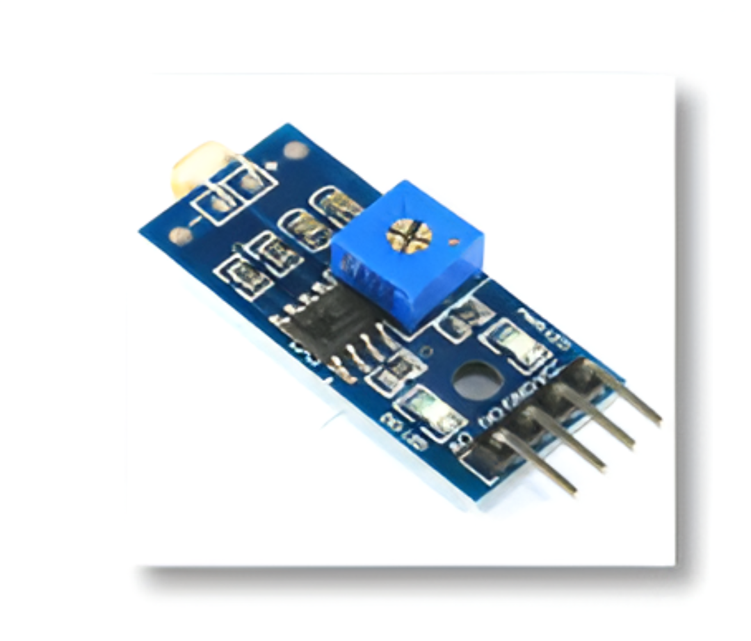
In the table 3.5.3, each pin configuration of LDR is listed with its purpose
| S.NO | Name | Purpose |
| 1 | VCC | Power pin of the sensor. It takes 5V power |
| 2 | GND | GND pin of the Arduino |
| 3 | A0 | Analog output pin receives and transmit IR waves. |
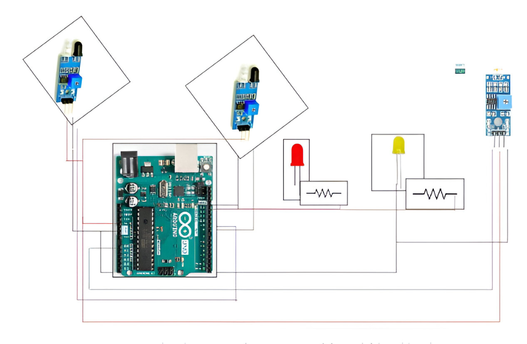
Subsection 3.5.3 Experimental Approach
Aside
-
Out pin is connected to 9th pin of the Arduino.
-
VCC of the IR sensor is connected to 5V of the Arduino.
-
GND of the IR1 sensor is connected to GND of the Arduino.
-
LED associated with IR sensor is connected to 13th pin of Arduino through a 10k resistor, shorter leg of Arduino is connected to ground.
-
IR2 sensor out pin is connected to 8th pin of the Arduino.
-
GND of the IR sensor is connected to GND of the Arduino.
-
VCC of the IR sensor is connected to 5v of the Arduino.
-
LED associated with IR2 is connected with LED is connected through 10k resistor to 12th pin of the Arduino.
-
A0 pin of LDR sensor is connected to A0 pin of Arduino.
-
VCC of the sensor is connected to 5V of the Arduino.
-
GND of the LDR sensor is connected to GND of the Arduino.
| Arduino Pins | Component Pins |
| D8 | out (IR_1) |
| 5V | + |
| GND | - |
| D9 | out(IR_2) |
| 5V | + |
| GND | - |
| D12 | +(LED_1) via 1K |
| GND | - |
| D13 | +(LED_2) via 1K |
| GND | - |
| GND | - |
| A0 | A0(LDR) |
| 5V | +VCC |
| GND | - |
Subsection 3.5.4 Code
Source codeint IR1 = 9;//declaring IR1
int IR2 = 8; //declaring IR1
int LED1 = 12; //declaring LED1
int LED2 = 13; //declaring LED2
int LDR = A2; //declaring LDR
void setup()
{
Serial.begin(9600);//initiate serial monitor
pinMode(LED1, OUTPUT);//mode declaration for LED1
pinMode(LED2, OUTPUT); mode declaration for LED2
pinMode(IR1, INPUT); mode declaration for IR1
pinMode(IR2, INPUT); mode declaration for IR2
pinMode(LDR, INPUT); mode declaration for LDR
}
void loop()
{
int LDRValue = analogRead(LDR);//convert the value of LDR
int IR_1=digitalRead(IR1);//convert value of IR1 to digital value and save as IR_1
int IR_2=digitalRead(IR2); convert value of IR2 to digital value and save as IR_2
Serial.println("sensor = ");
Serial.println(LDRValue);
delay(500);
if (LDRValue > 800)//if LDRValue is greater than 800
{
digitalWrite(LED1, LOW);//set led to LOW state
digitalWrite(LED2, LOW); set led to LOW state
}
if (LDRValue < 500 || IR_1 == HIGH) if LDRValue is <500 and IR_1 ==1
{
digitalWrite(LED1, HIGH);// set led to HIGH state
}
if (LDRValue < 500 || IR_2 == HIGH) if LDRValue is <500 and IR_2 ==1
{
digitalWrite(LED2, HIGH); set led to LOW state
}
}
-
Declaring variables of IR_1 to 9th pin of the Arduino, IR_2 to 8th pin of the Arduino, LDR to A0 pin of the Arduino, LED1 to 12th pin and LED to 13th pin of Arduino respectively.
-
In void setup () declaring the input Pins IR1,IR2 and LDR pin using PinMode function.
-
Be sure which of the following acts as input and output pin, pinMode(IR1, INPUT); pinMode(IR2, INPUT); pinMode(LDR, INPUT),declaring the LED pin as Output using PinMode function.
-
In void loop function, using analogRead function will convert the LDR value generated from the sensor to analog value.
-
Generated analog value will be stored in an integer variable.
-
Using digital read function will convert the values from IR sensor to a digital value and store it in an integer variable called IR_1 and IR_2.
-
This prototype will work according to the following conditions. When the LDR i.e., Light intensity value of the sensor id greater than 500 the LED remains in off state.
-
If intensity value is high or if there is an object in the street the LED will turn on. If any one of the conditions is true the LED will be high
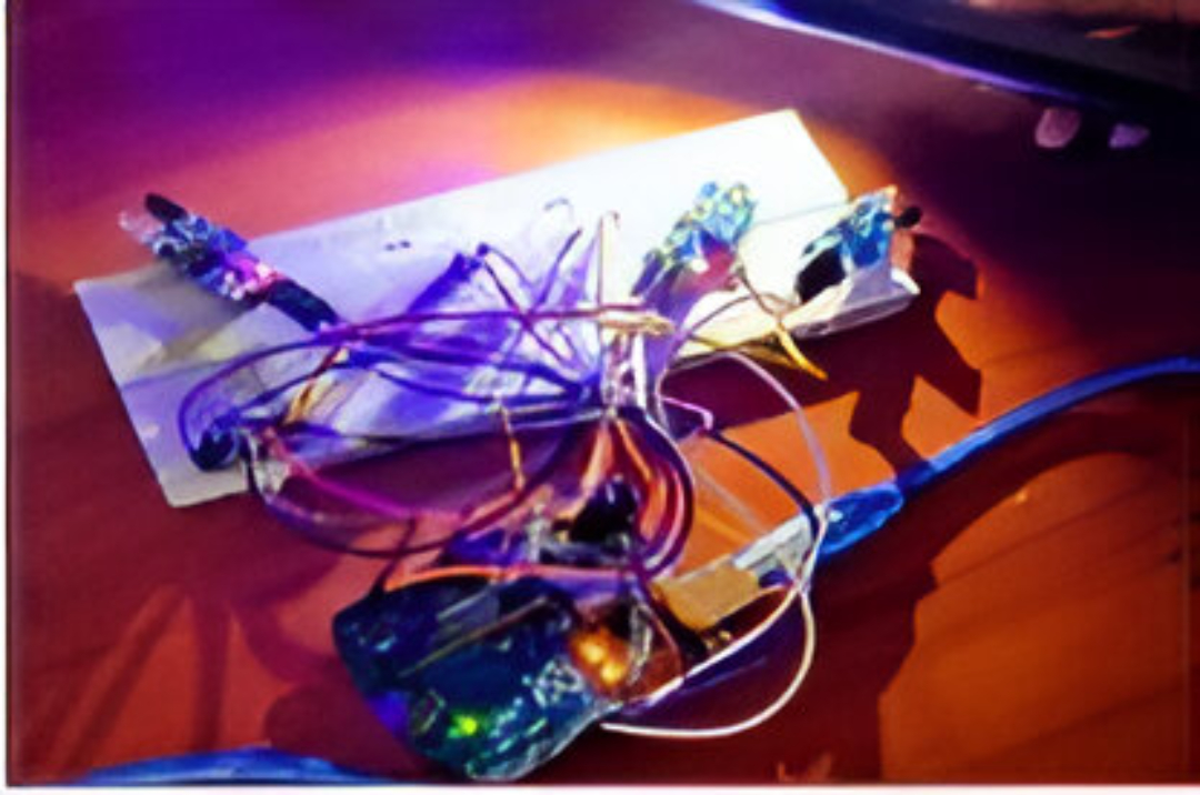
Subsection 3.5.5 Experimental Result
From the below fig 3.5.6, when the light intensity from the external force is less than 500 and when IR1 and IR2 sensor finds the object, the light intensity will vary from the threshold, therefore the two LED will be set to high
You have attempted of activities on this page.
